 |
Sapia
Incorporated Modbus Software Components for Developers |
|
|
Test |
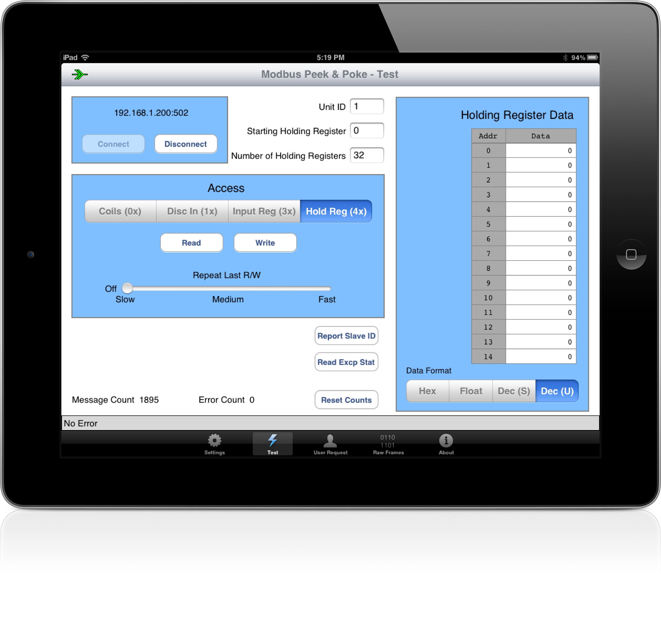
The Test tab provides access to the registers, discretes and coils of your Modbus/TCP device.
Connect
Tapping on the Connect button will attempt to connect to the specified Modbus/TCP server using the specified listen port and connection timeout value. If the connection is successful, the connection status icon in the upper left corner on the title banner will change to connected green arrows and a corresponding status message will be displayed on the status bar at the bottom.
|
|
Connected status icon |
Disconnect
Tapping on the Disconnect button will disconnect from the specified Modbus/TCP server. The connection status icon in the upper left corner on the title banner will change to disconnected red arrows and a corresponding status message will be displayed on the status bar at the bottom.
|
|
Disonnected status icon |
Uint ID
This field specifies the decimal Unit ID for all requests. For most Modbus/TCP devices, a value of 1 should be used here. If you are communicating out through a Modbus/TCP to Modbus/RTU gateway, this field must be set to the slave address for the specific Modbus/RTU device that you want to address. Valid values are 0 (broadcast) to 255.
Starting XXX
This field specifies the decimal starting register, discrete or coil to be read or written depending on what Access type is currently selected. Valid values are 0 to 65535.
Number of XXX
This field specifies the decimal number of registers, discretes or coils to be read or written depending on what Access type is currently selected. Valid values are 1 to 2040 for discretes and coils, or 1 to 127 for registers.
Data Grid/Data Format
The data grid is used for displaying and entering data associated with the current Modbus/TCP function. Data can be displayed or entered in hexadecimal (Hex), floating point (Float), signed decimal (Dec(S)) and unsigned decimal (Dec(U)).
Access
This selection specifies the register type to access using the read and write buttons. The following table relates the Modbus function code used in the the request with the other controls on the Test tab.
| Access Button Selected | Read/Write Button Selected | Number of XXX Value | Modbus Function Code (decimal) |
| Coils (0x) | Write | >1 | 15 - Force Multiple Coils |
| Write | 1 | 05 - Force Single Coil | |
| Read | >=1 | 01 - Read Coils Status | |
| Disc In (1x) | Read | >=1 | 02 - Read Input Status |
| Input Reg (3x) | Read | >=1 | 04 - Read Input Registers |
| Hold Reg (4x) | Write | >1 | 16 - Preset Multiple Registers |
| Write | 1 | 06 - Preset Single Register | |
| Read | >=1 | 03 - Read Holding Registers |
Read
Tapping this button sends a read request to the Modbus/TCP device and displays the returned data in the data grid control. The function code used depends on the Access type and other parameters as shown in the table above.
Write
Tapping this button sends a write request to the Modbus/TCP device using the data currently entered into the data grid control. The function code used depends on the Access type and other parameters as shown in the table above. The Write button is only enabled when either Coils or Holding Registers are selected.
Repeat Last R/W
This slider control can be used to continuosly repeat the last read or write function. The message rate will vary with your network speed and Modbus/TCP device speed. Returning the slider to the far left will turn off this feature.
Report Slave ID
Tapping on this button sends the Report Slave ID function code (decimal 17) to the Modbus/TCP device. Not all devices support this function code. If supported, a variable number of bytes are returned in the response and displayed in the data grid.
Read Excp Stat
Tapping on this button sends the Read Exception Status function code (decimal 7) to the Modbus/TCP device. Not all devices support this function code. If supported, a single byte is returned in the response and displayed in the data grid.
Reset Counts
Tapping on this button resets the Message Count and Error Count values to 0.

![]()
Send mail to
webmaster@sapia-inc.com with questions or comments about this web
site.
Copyright © 2023 Sapia, Incorporated
Last modified: May 25, 2023